As noted in Drill Press Sharpening Station the speed of the Craftsman drill press is much too fast, unless you are drilling small holes. So a speed reducer is needed to cut the speed, ideally by four, 1200 ⇒ 300 rpm. I looked on the web for ways other people have inserted speed reducing pulleys into the pulley trains on drill presses. In the one that seemed most amenable to my drill press a shaft was held in the column top. An arm came off of that shaft. At its far end it supported an adjustable pulley stack. The arm would automatically position itself to equalize the belt tension on the two belts; one from the motor and one to the spindle.
There is not much room inside the housing so I am considering an alternative. Instead of using an arm to offset the spindle bearing shaft. I will just put the shaft in the column, but off center. The cylinder holding the shaft in the column can be rotated to allow the belts to equalize tension. I am not sure it will be sufficient movement, but I want to try it.
For this project two parts need to be fabricated and three purchased. A pulley stack and two bronze bearings need to be purchased. The bearings will be attached in the pulley stack and will reduce the ID from 3/4" to 1/2". The pulley stack will sit on a shoulder bolt. The shoulder bolt will be screwed into the cylinder mount. This mount will fit in the column and will be held in place by 1-3 screws. The column is 2" ID.
With a 2" column ID the largest offset for a 1/2" shaft is 5/8" leaving 1/8" outside the shaft. If the belt lengths can be made pretty exact this should be sufficient. I have a course in Fusion 360 this weekend. I am going to go through a tutorial first. I will use this project to learn Fusion and design the parts.
I did purchase a length of 2" steel round this morning and a large piece of leather. A 2" length of the steel was cut off with the bandsaw. It was faced on both ends. It is hot rolled steel and slightly oversized. The diameter was reduced getting rid of most of the corrosion. It is an easy fit in the column. Purchasing a larger diameter was expensive and not necessary. I picked up a steel plate from Warner Steel along with the round. This plate will be cut to size and bolted to the rod to hold it in place on the column. Putting holes in the column looks problematic. I may only use one set screw to hold the rod in place. I think I can drill the back side of the column.
The steel rod was drilled and tapped for three screws. The bolt circle was marked out about 3/16" from the outside of the rod. The rod was mounted on the centered dividing table. It was centered by eye using the marked rod center and an edge finder. The table was moved to be over the bolt circle. It was difficult to hold the rod down with two strap clamps. The first hole was drilled with a #29 drill to 5/8". It was tapped 8-36. The table was rotated 120° and the second hole was drilled. The rod came loose! The hole was completed and tapped, but now the third hole's location had to be guessed.
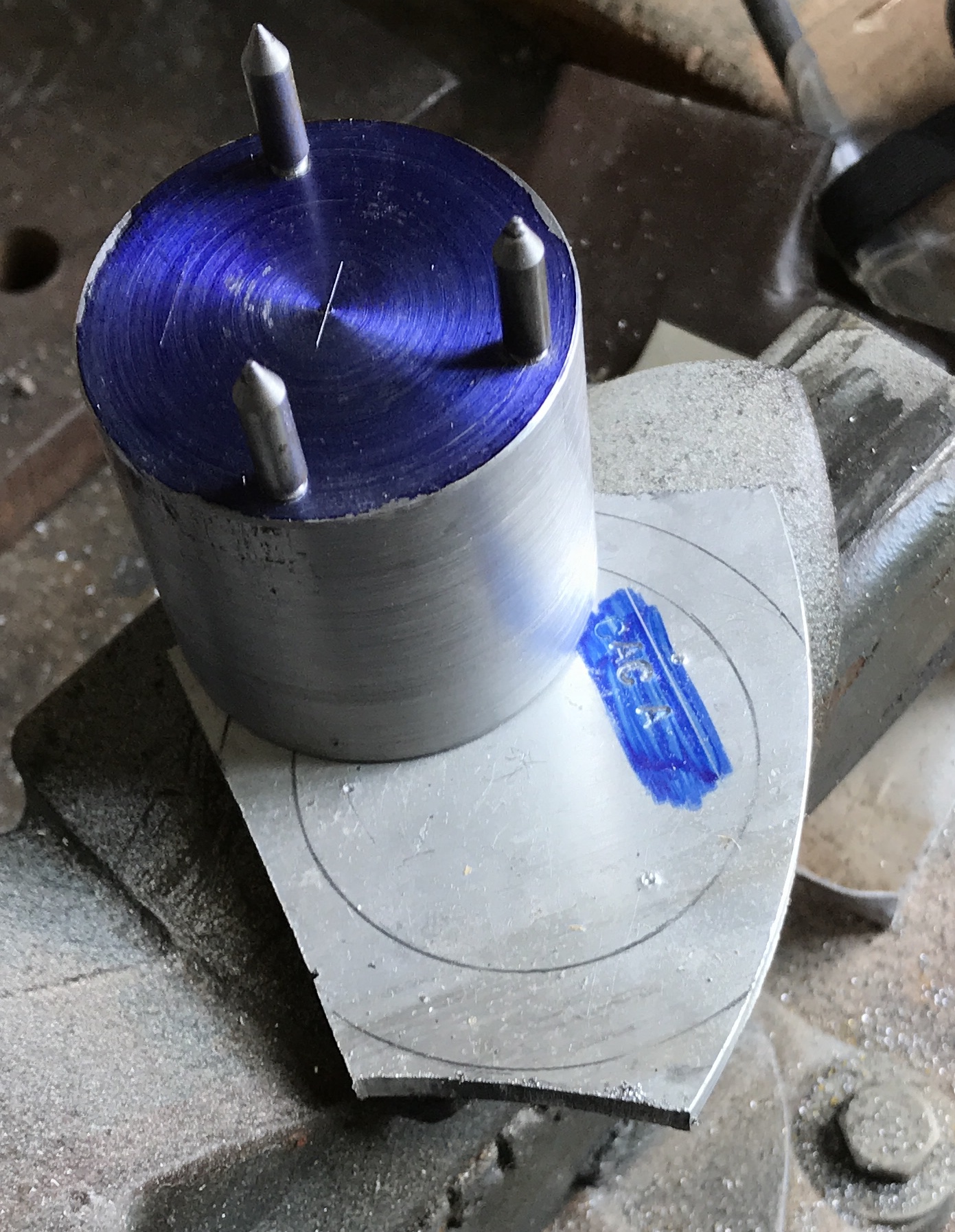
After trying to make a cap from a piece of 1/4" steel the attempt was abandoned. The band saw blade went dull and another blade needs to be ordered. I switched to aluminum. An old scrap was located and marked out for a 2 1/2" circle. A few corners were cut off with a hacksaw. The holes were transferred from the rod to the aluminum cap. This was done with three of the hardened points used for the orrery. They were screwed into the holes. The aluminum cap was set under the points and the rod was smacked with a heavy ball peen hammer. The transfer can be seen in the photo below.
The aluminum plate was clamped to the top of the vise with strap clamps. Through holes were drilled with a #10 drill. As the spindle was centered over the hole a 3/8" end mill was used to make a 1/8" countersink. There was a lot of chatter until the end mill had penetrated the aluminum. I forgot that the transfer was essentially done on the back side of the plate. It would not have made a difference, if the bolt circle had been correctly made. In this case one of the three holes was not aligned. With the top mounted a fourth hole was drilled and tapped in the steel rod. The plate was reduced to a circle, faced and the edges were chamfered. The photo shows the result.
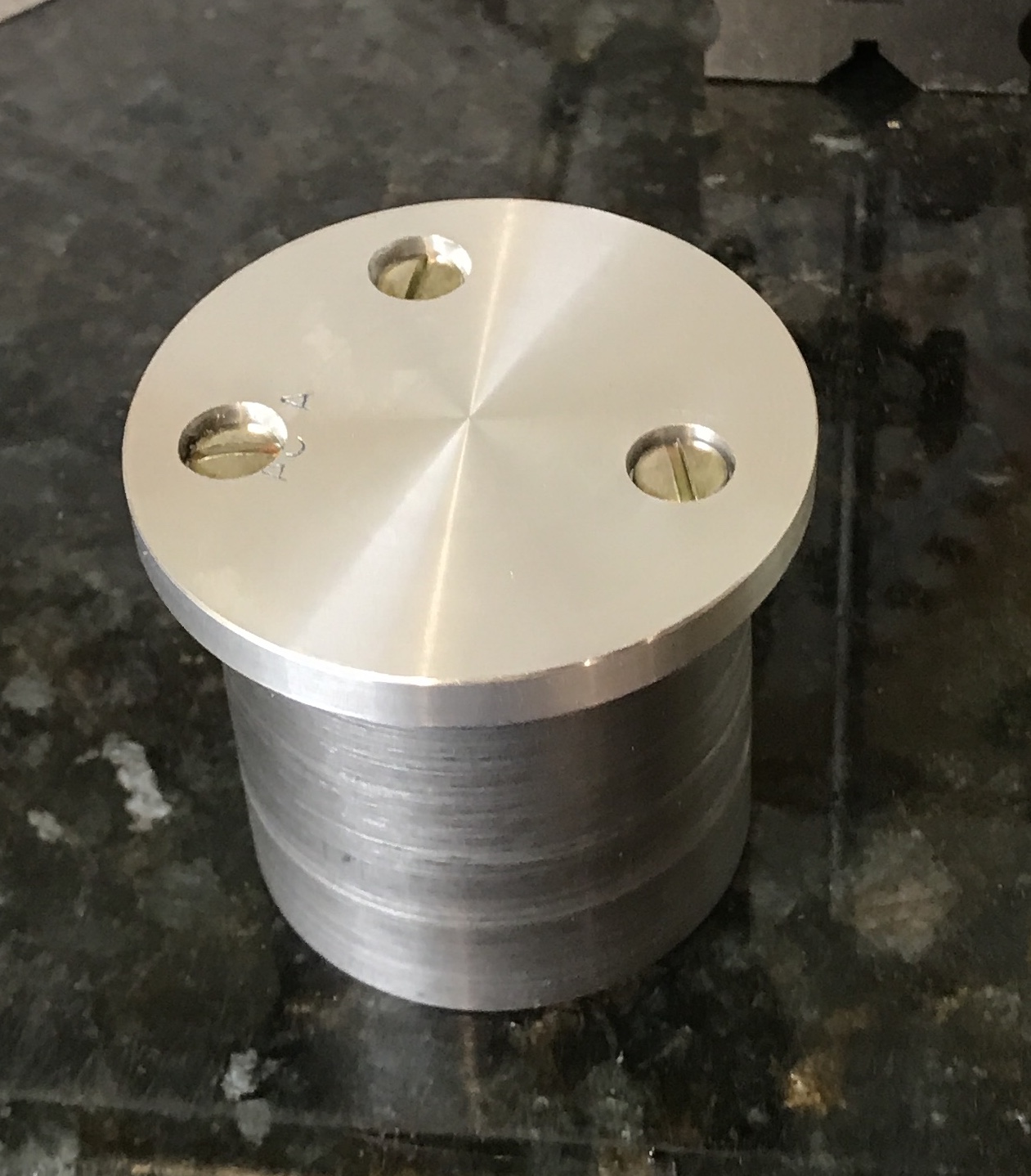
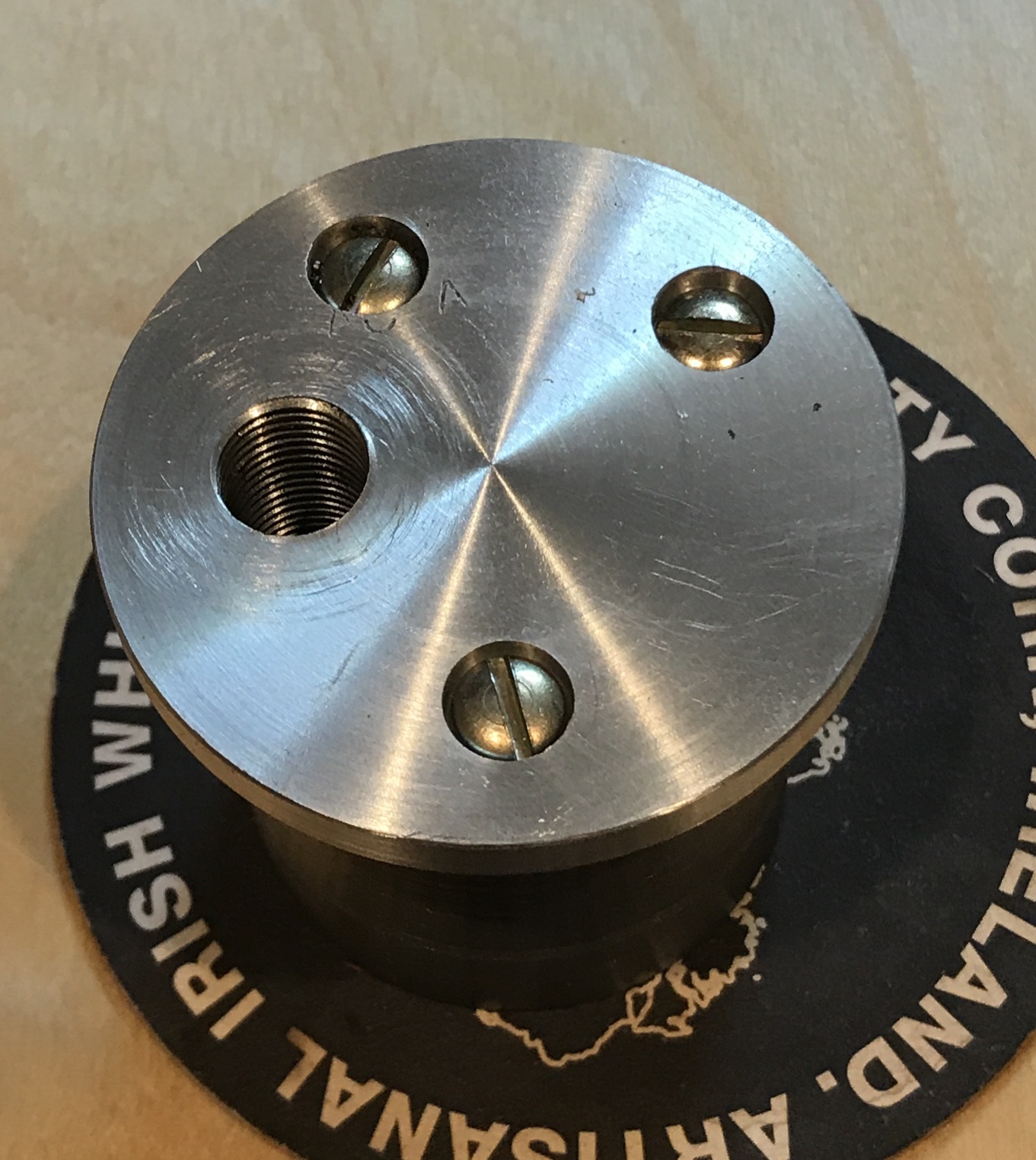
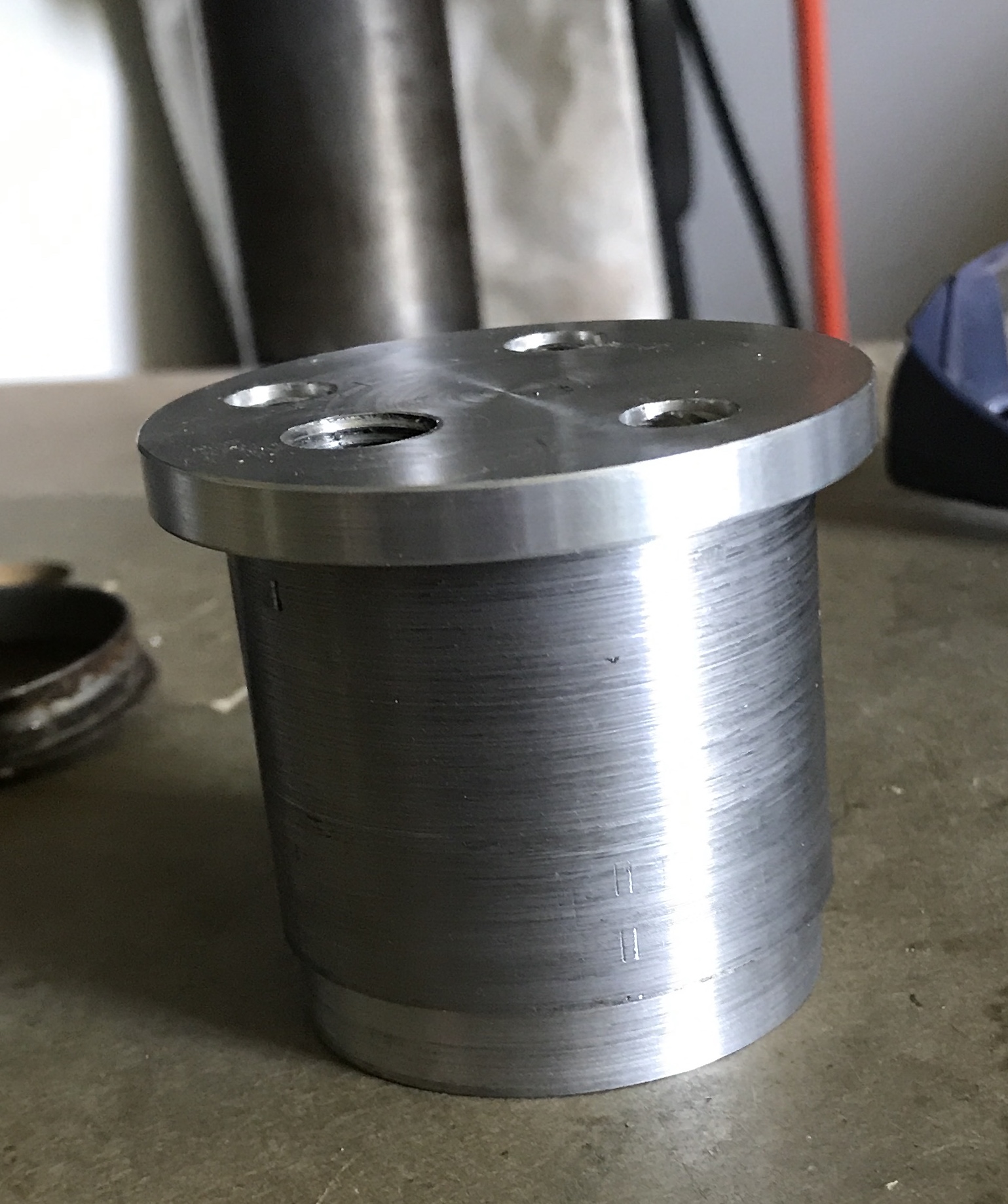
The aluminum cap was marked for the threaded hole. The mark was 5/8" from the center and midway between two holes. I made sure the unused hole did not interfere. The marked location was centered in the four-jaw chuck on the South Bend lathe. A tailstock center was used to center it. The hole was centered drilled and then drilled up to 29/64". The drilling went very smoothly. A 1/2-20 tap was started with the part still on the lathe. It was then transferred to the vise and the threads were cut all the way through the hole. Both ends of the hole were chamfered. The photo below shows the completed cylinder mount.
The cylinder mount did not fit in the cylinder. It stopped about 1 5/8" down. Upon closer inspection the cylinder was bored part way down and slightly off center. I removed about 0.08" from the diameter of the lower 3/8". This allowed the mount to fit and rotate freely. The step pulley, two Oilite bearings, and the adjustable v-belt were ordered this morning from McMaster-Carr.
The bearings from McMaster were not quite as expected. I expected to get oversized on the OD and undersized on the ID. Then they would be machined to size. The OD is slightly oversized at 0.752". The ID is also oversized at 0.502". This is not an issue as I can make the shaft to fit the ID. Turns out the ID of the pulley is 0.754"! It is already a nice sliding fit on the bearings! I guess I need to pay closer attention to McMaster-Carr's blueprints. I will make these bearings a press fit on the shaft, instead.
A 5" length of 5/8" steel hex was located. It was center drilled and held between the three jaw chuck and the half-center. The end was faced. It was reduced to a little over 0.5" for 4 1/2". The 2" closest to the headstock were reduced very carefully to 0.5025". The 2 1/4" at the tailstock end were reduced to 0.498". A thread stop was cut at 2 1/4", though it is probably unnecessary. The tailstock end was threaded 1/2-20 in the vice. The shaft was parted off at 4 1/16" The parted end was drilled and tapped 10-32 to a depth of 3/4".
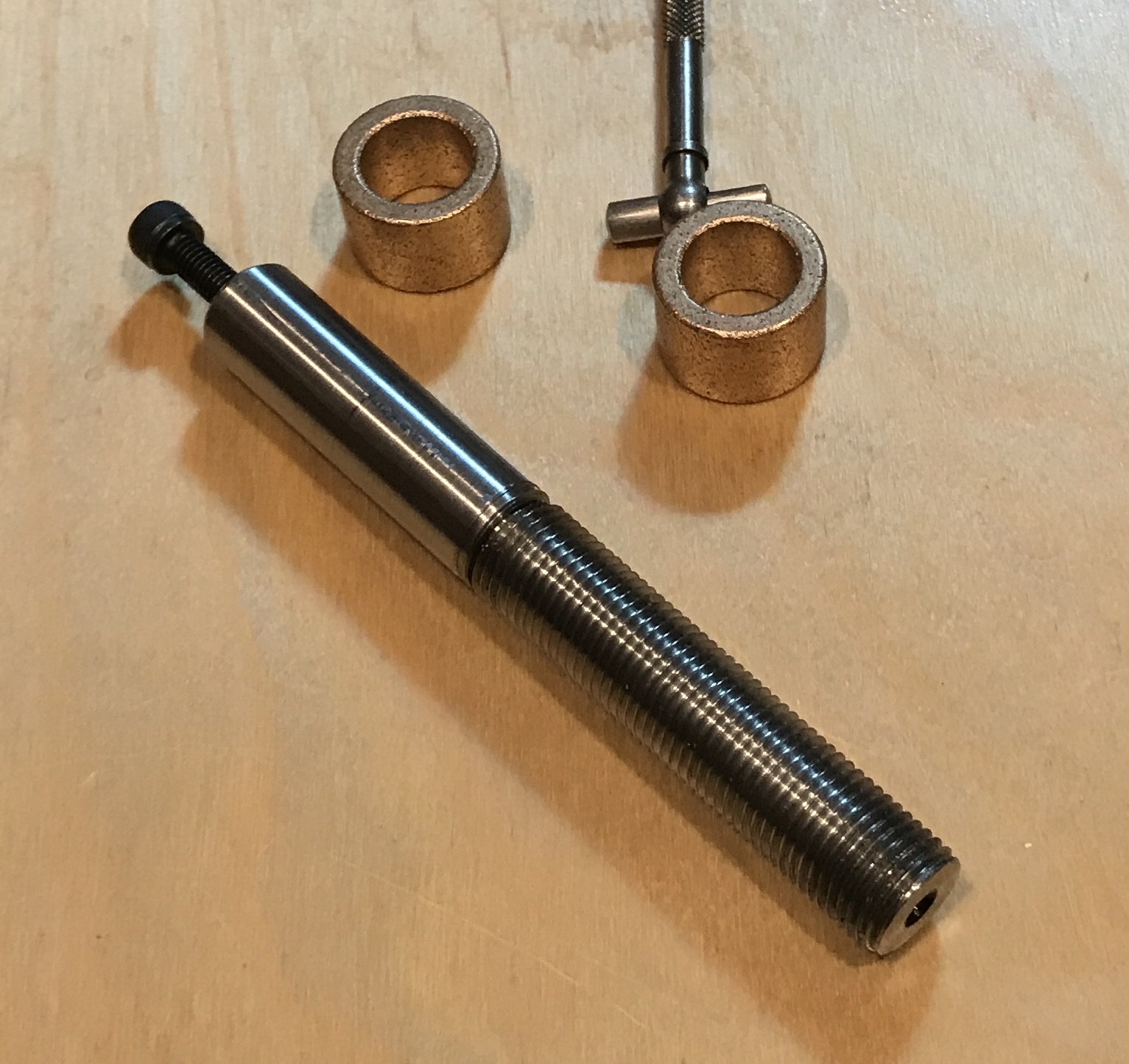
A collar was made to hold the pulley onto the shaft. A 1/4" piece of 1 1/4" round bronze was found. A hole was drilled through 7/32". A mandrel was quickly made and the outside of the collar was reduced until it was concentric with the center hole. The corners were chamfered. A washer for the pulley to sit on was also made. A 1/32" ring of 1" round brass scrap was parted off after drilling 1/2" and facing.
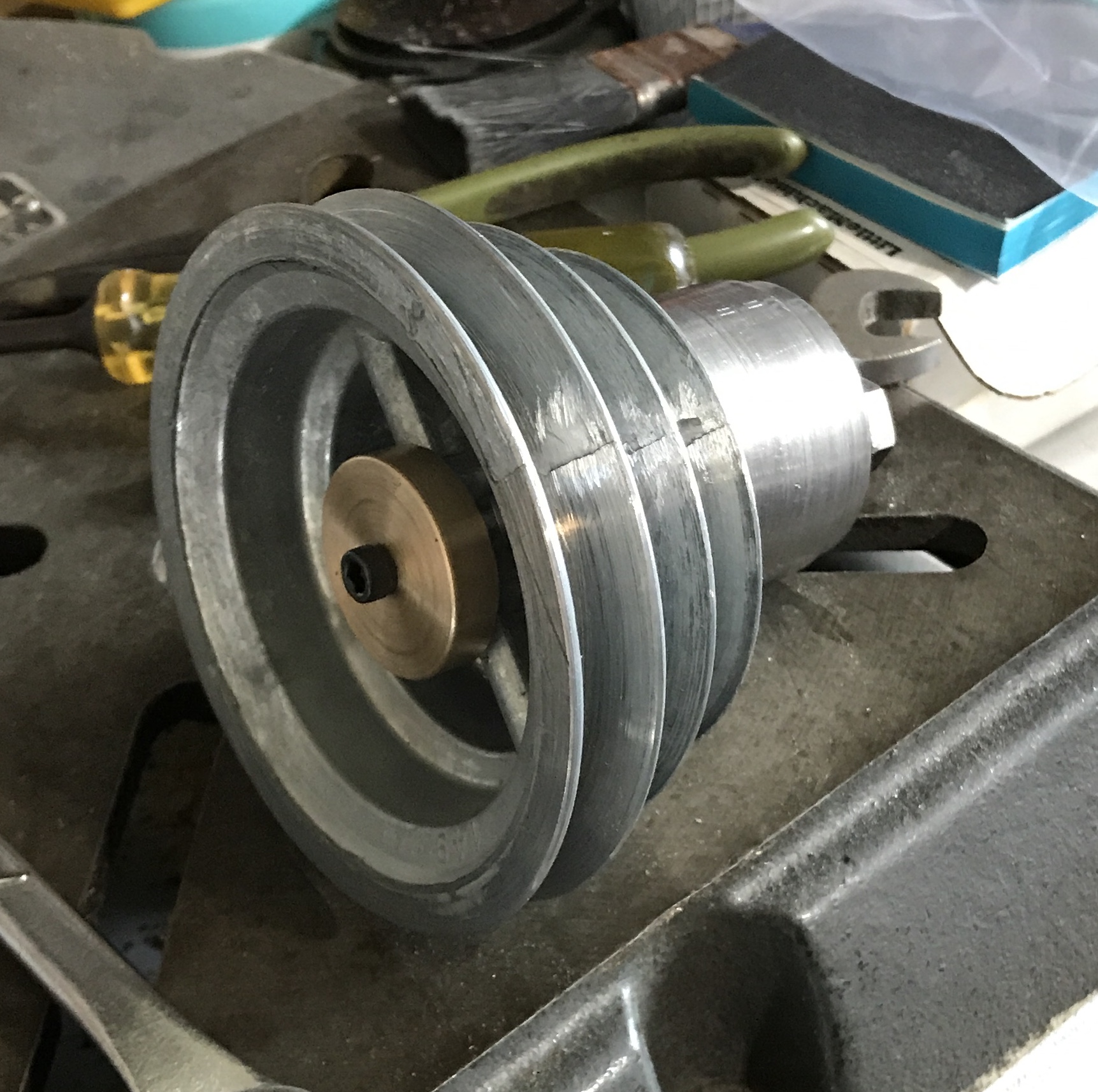
After looking at the pulley I realized I had made a mistake. The pulley is 1 3/4" high, but the internal hole is only 1" high. So the bearings were pressed on the screw end using an aluminum tube and the garage vise. The unused end of the shaft was cut off with a hacksaw. The new end was faced, drilled, and tapped as before. Now it is a decent fit. The pulley does not spin freely. The bottom is not very flat. It needs to be faced.
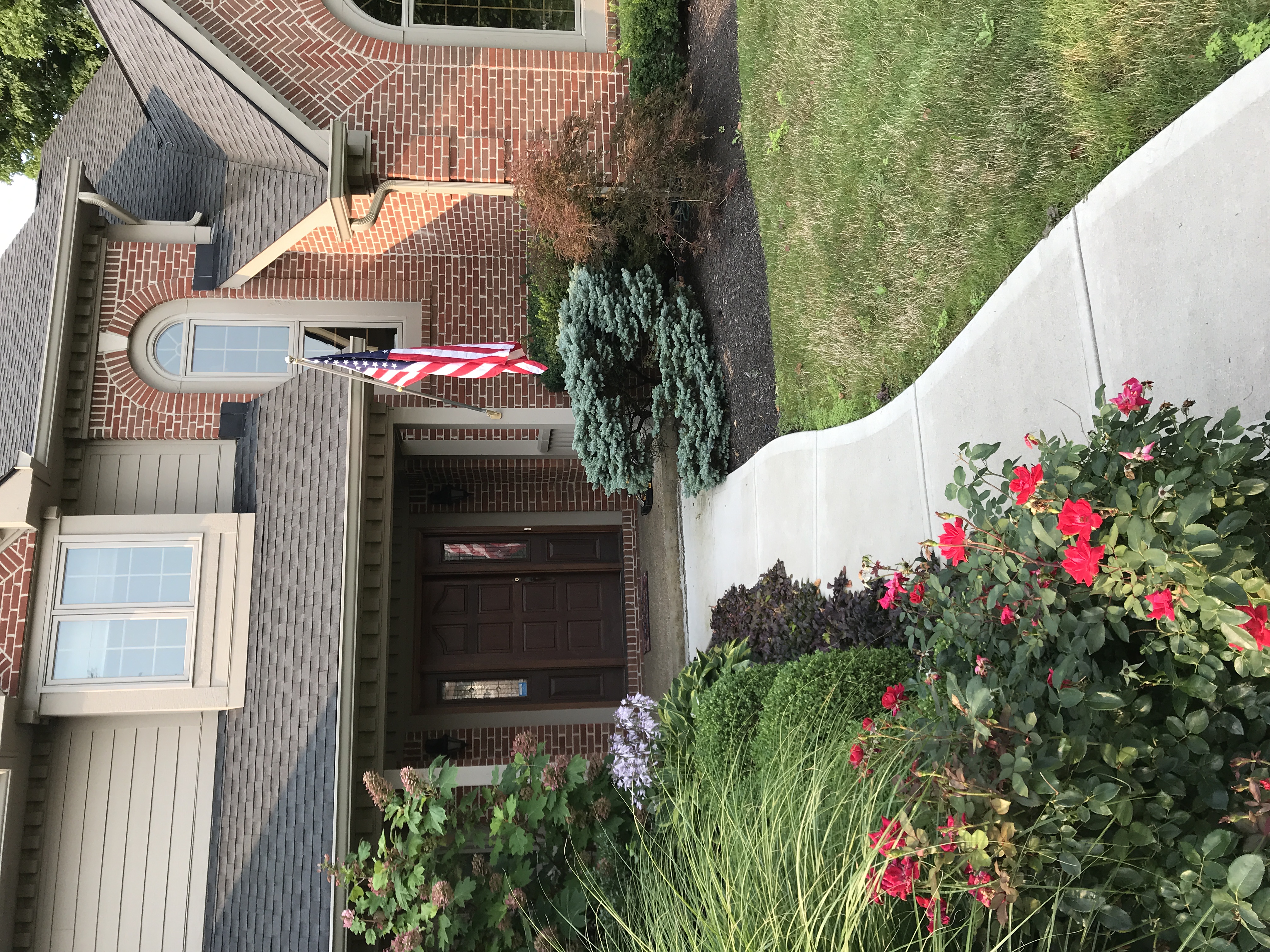
Took a brief respite from speed reduction and raised the flag. I picked up Sylvia's flag. Heshe had it up at their last house. It has been in storage at the Stratford ever since. It was quick to put up. It seems like a very strong holder. Let's hope it will survive thunder storm force winds.
Today was the day to put it all together. First the length of the column support was reduced by an 1/8" in the lathe. Second the pulley was flattened by sanding on 80 grit paper. All of the threads and the column support exterior were oiled before assembly. After assembling the column support was dropped into the column.
I was unable to raise the motor by hand. I used a ladder to get above the motor, but was unable to pull it up the inch or so that was available. I turned the table around and moved it up under the motor. Rhea's car actually has a jack. I used that with a small steel block on it to push the motor up to the top of its travel. It took more time to get the jack out and return it, than using it. The screws holding the motor were tightened. The screws that allow the motor to move and tension the belt were loosened. The motor was pushed all the way in toward the spindle.
The adjustable belt was studied and came apart easily with needle nose pliers. The belt from the spindle to the new pulley was made to fit the bottom groove on both pulleys. This is where I ran into the first problem. With the belt in place it was readily apparent that the bottom groove on the spindle pulley was below the bottom groove on the speed reducing pulley. The bottom groove on the speed reducing pulley was level with the next groove up on the spindle pulley. I resized the belt. I wanted to see if this even worked before attempting to raise the spindle pulley.
The pulley on the motor shaft was raised so its top was level with the top of the speed reducing pulley. The second problem arose as I attempted to make the belt from the motor pulley to the speed reducing pulley. I didn't have enough links!!! Off to Amazon to buy pulley pullers and more adjustable belt!
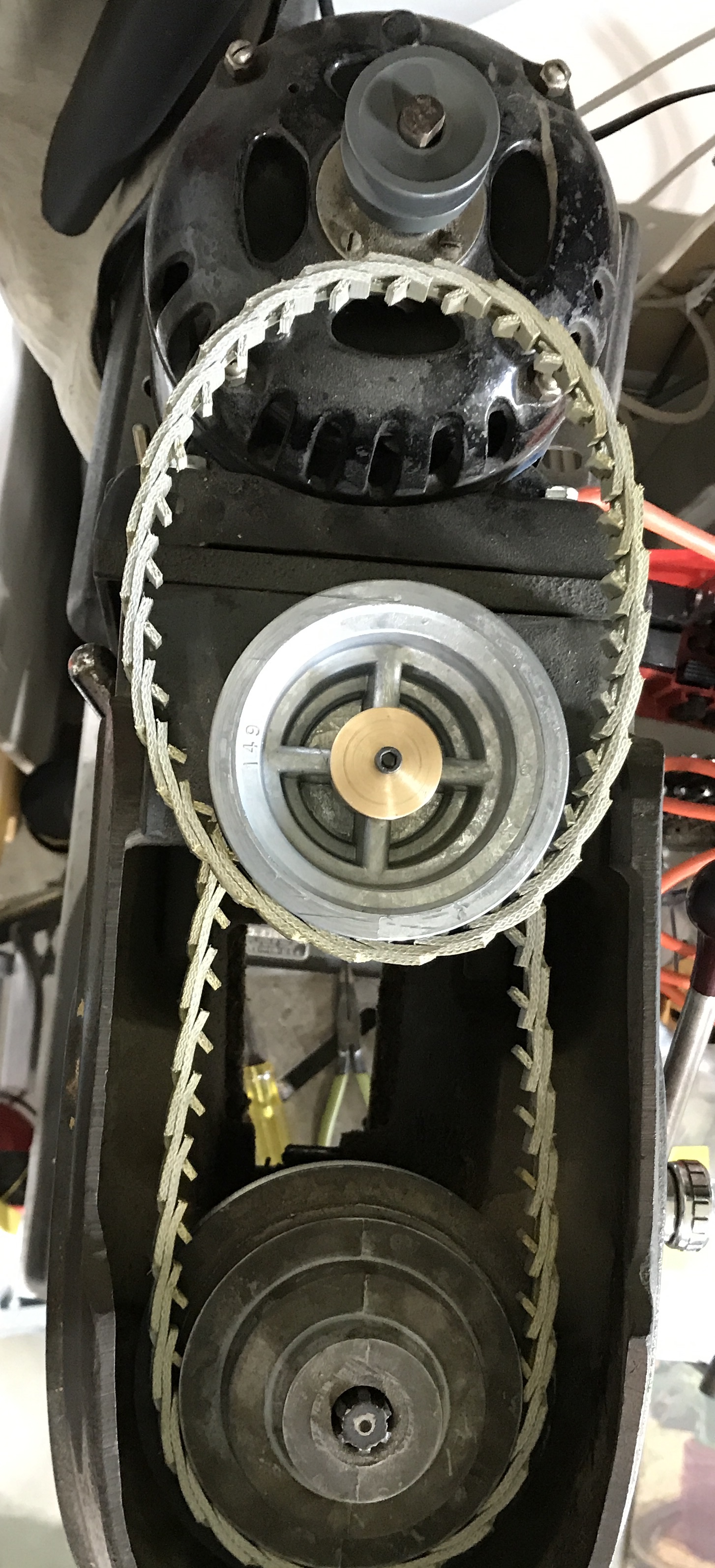
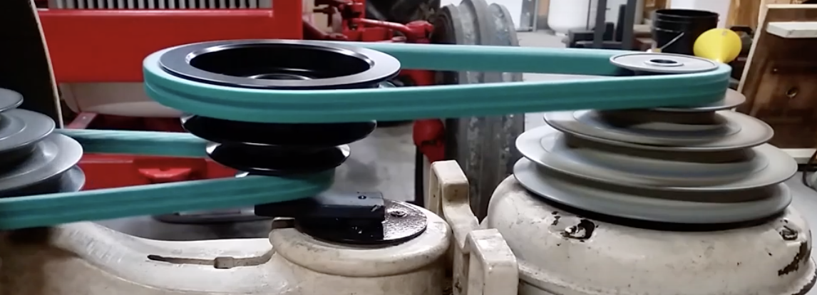
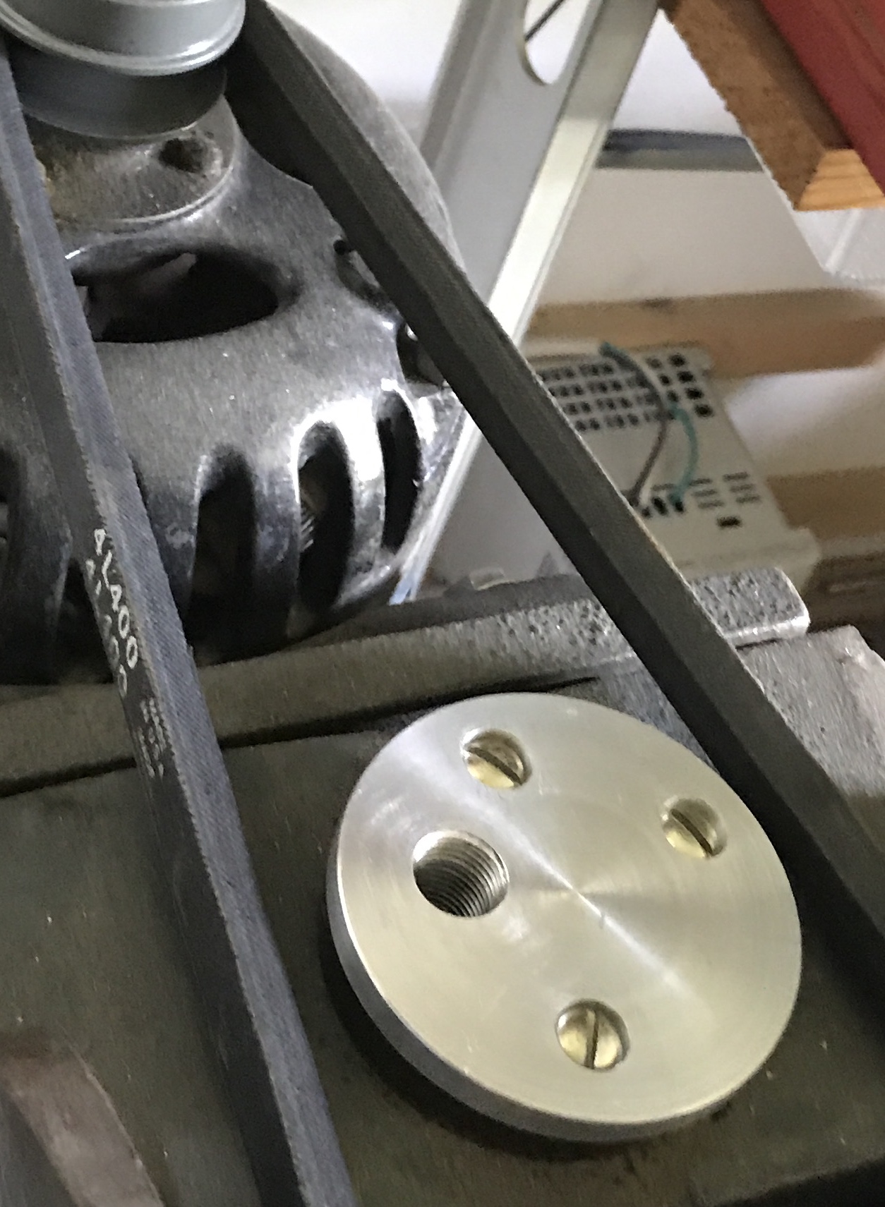
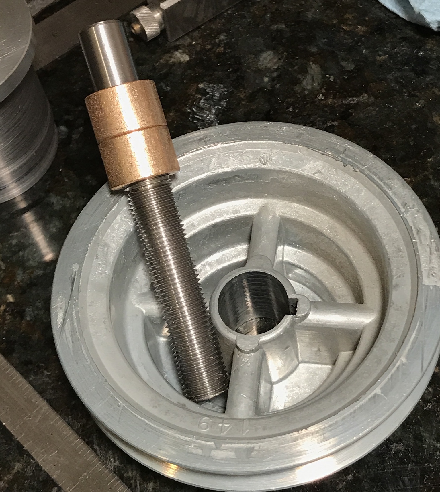
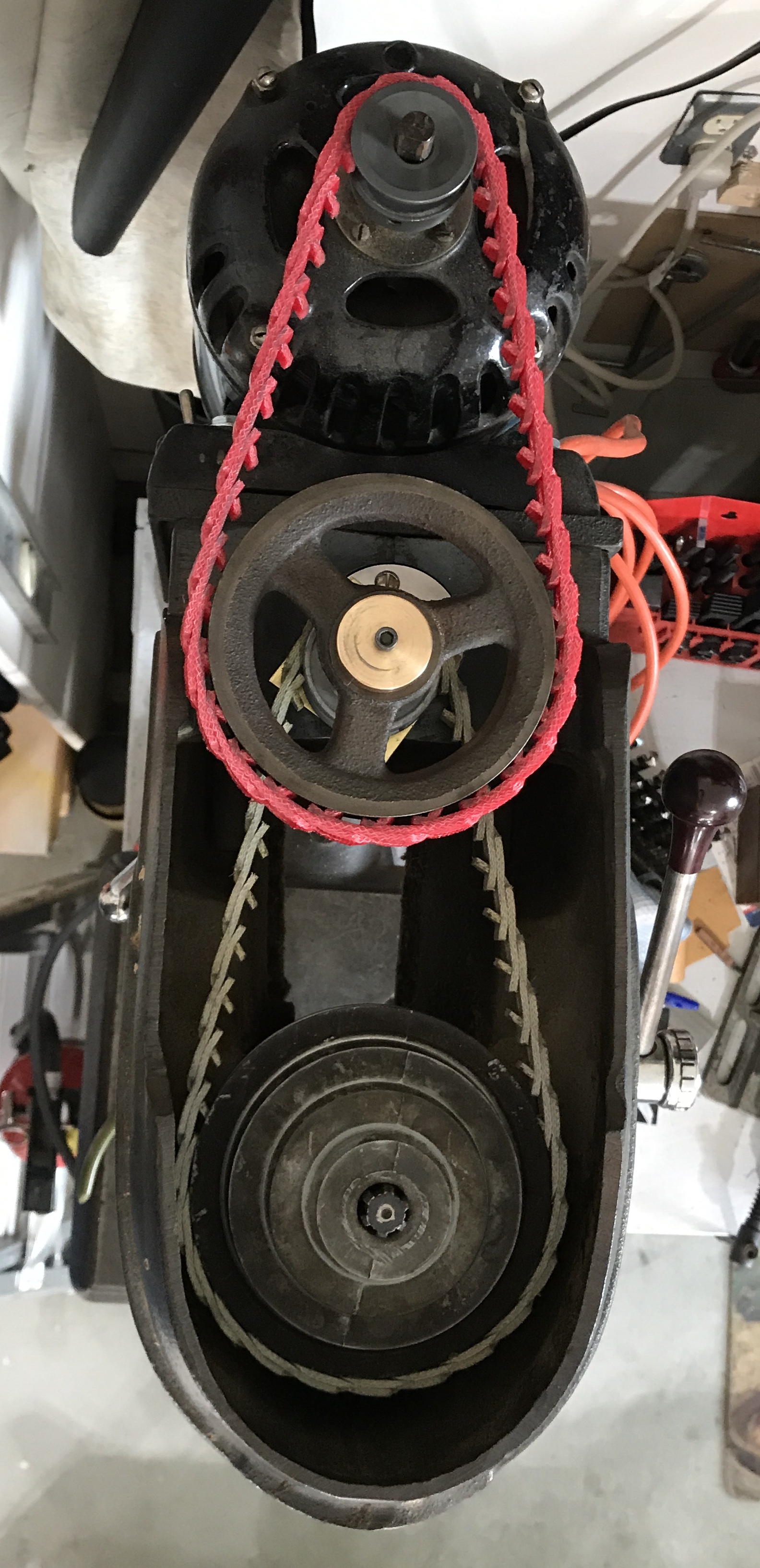
The spindle pulley cannot be raised. It is a press fit on a cone that is slotted on the inside and drives the spindle. It is possible the cone could be raised, but I prefer not to remove the pulley from the spindle. I wanted to try out the current configuration. The belt from the motor to the idler pulley was expanded by three links. The belt was reinstalled and everything worked well (shown above). The speed was about 1100 rpm!!! There was effectively no change in spindle speed. This is probably due to the large size of the idler pulley driving the spindle and the smaller size of the pulley on the spindle. I need different pulleys.
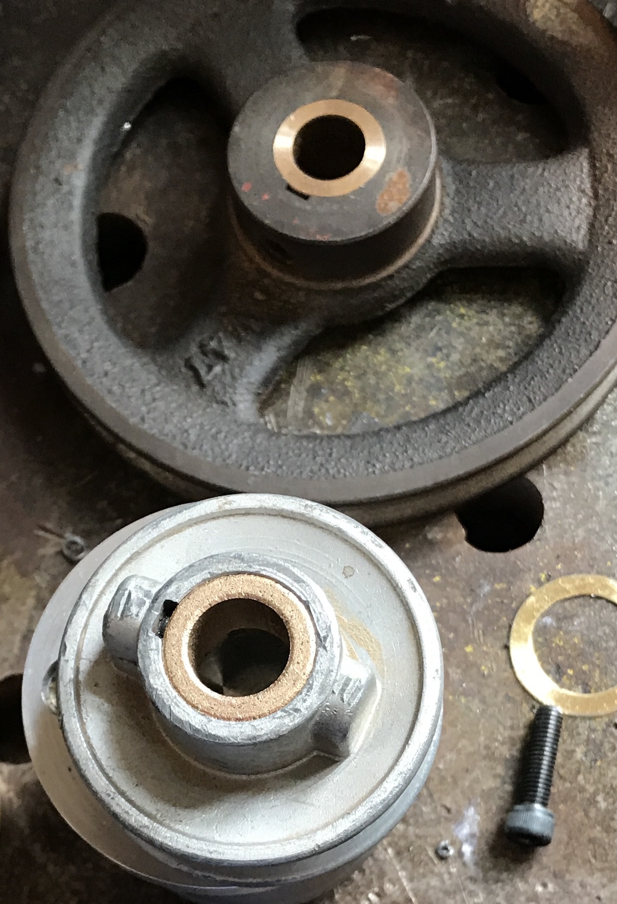
I have three pulleys that might suffice. The ID of the 4" pulley is 0.628. The ID's of the two 1" pulleys are 0.500" and 0.624". These pulleys are shown below.
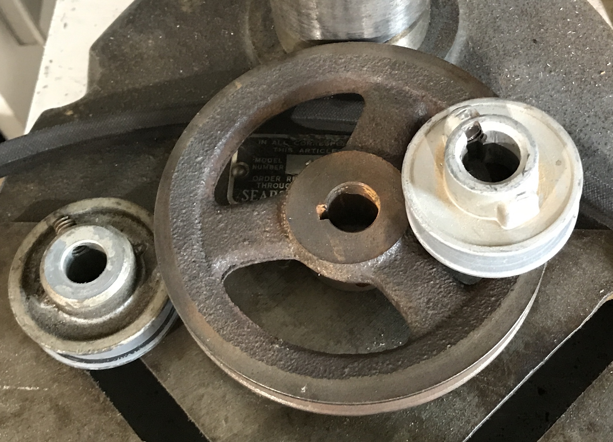
I will make a new shaft. The shaft needs to be 4" long. The bearings need to be removed from the current shaft. The bearings will also need to be reduced for a sliding fit in the new pulleys. A spacer may not be needed to keep the pulleys at the correct height. The two pulleys have wide center portions holding the set screws. Putting these together may serve as the spacer. This wide center may also allow an easy way to keep the pulleys fixed to one another. Connecting these two while keeping the pulleys concentric will pose a challenge.
Looking at the head of the drill press provided some more ideas. One of the problems has been not being able to use the belt on the largest and lowest pulley on the spindle. This is because the drill press support column rises above the level of this pulley by about 3/8". If I raise the drill press head 1/2 to 5/8" the lowest pulley on the idler shaft will be in line with this pulley. The idler shaft support could be dropped into the support column. The current cap would need to be reduced in one or two dimensions to continue to keep the shaft support from dropping into the column, while fitting into the opening. I will need to use the CRV's car jack to raise the drill press head.
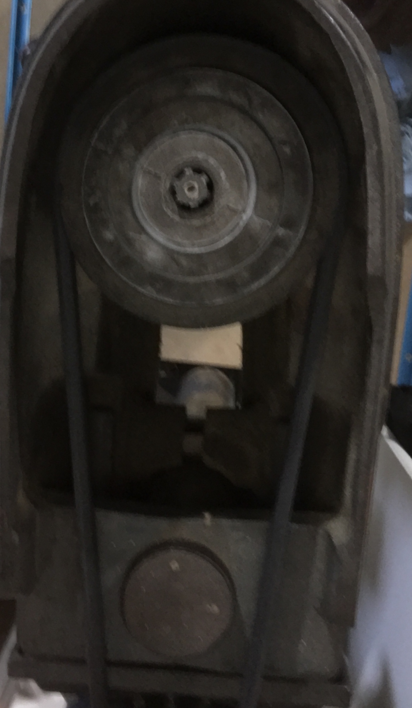
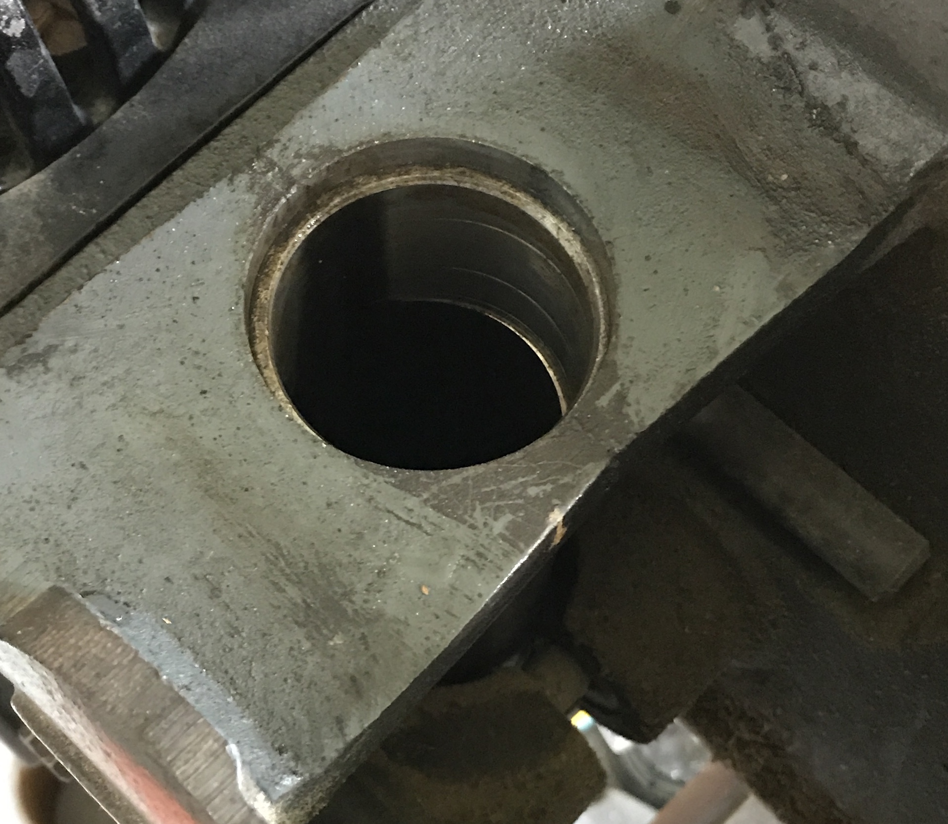
Success! The jack was positioned between the raised table and the head as close to the column as possible. A block of wood was placed on top of the jack as the top of the jack was too small and fit between the two sides of the head. The head did not budge after loosening the cross bolt. WD-40 was applied to the top of the column and just beneath the head. I still got no movement with the jack. I pushed on the front of the drill head and it rotated. The jack was then able to raise and lower the head. I raised it sufficiently so that the column was 1/4" below the top as shown in the photo below. The cross bolt was tightened.
The inside of the column housing was measured to be 2.235". The column support was returned to the lathe with the top still attached. The top was reduced to 2.232". The top of the column support was a nice sliding fit in the column opening.
The shaft needs to be remade. The threads should be 2 1/2" long and the total length is 5". I could only find some 5/8" rod that is poor quality. The machining was done on the South Bend lathe after center drilling. The shaft was held between the 3-jaw chuck and a tailstock center. It was turned down to 0.500". The finish was awful so I decided to press fit the bearings into the pulleys. The free end of the shaft was threaded 1/2-20. It was such a tight fit in the column support that it could only be threaded about 1" in. With the die in the holder the screws in the holder were tightened. The shaft was rethreaded. This time the shaft screwed easily into the column support, maybe even too easy.
The pulleys needed to be bored for the bearings. Both pulleys had 5/8" ID's. The large pulley was set up in the South Bend three-jaw chuck with the jaws between spokes and pulling out on the wheel. The bore was not quite concentric with this method of clamping, but it was only off by about 0.005" or so. The holes were bored 1/2" deep using the stop. The hole was bored to 0.7515" for a nice force fit of the bearing. The second pulley was bored similarly, but was set up normally in the vise using parallels and aluminum jaws. It was bored slightly oversized. The set screw was used to secure the bearing. Now the pulleys need a shaft or key to keep then in sync.
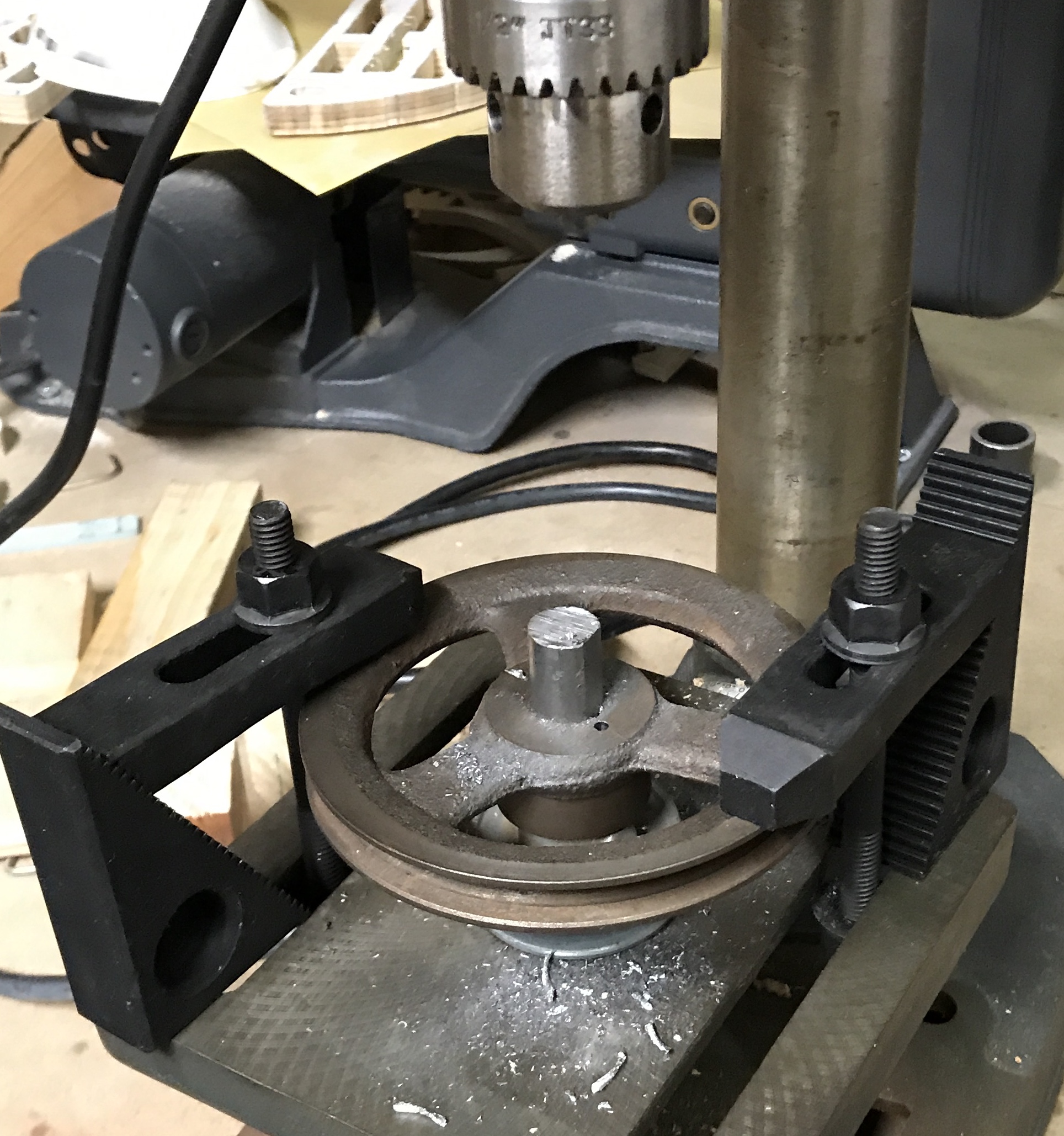
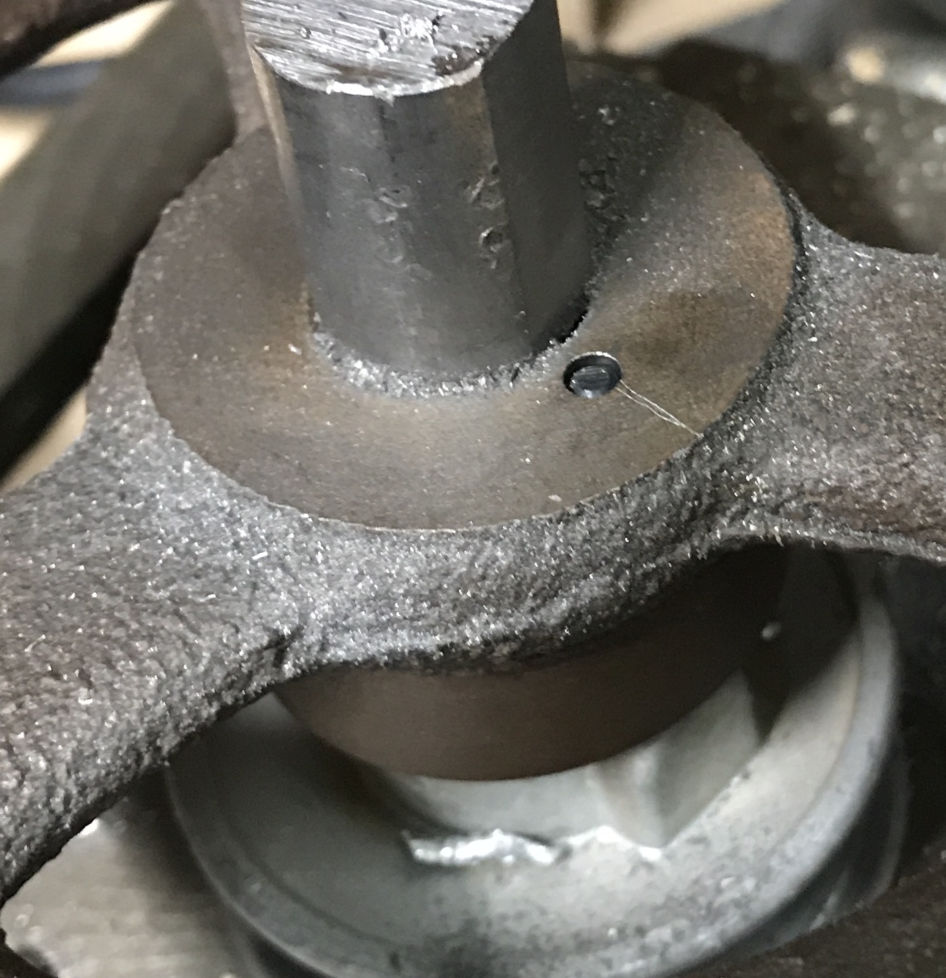
To drill the pulleys a few things needed to be done first. The location of the hole was determined by the extra bump on the flange of the small pulley. It allowed a 1/8" hole that was next to the outer edge of the bearing. The measurement was transfered to the larger pulley as it had a nice flat for drilling. The pulleys were clamped to the drill press table. Two large step blocks and strap clamps were used to hold the two pulleys down. The pulleys were held concentric by inserting the column shaft through them. The column shaft still had the unmachined 5/8" diameter end, which kept the shaft from falling through. This stuck out in the way of the drill, however, so a flat was filed on this part of the shaft. The lower pulley bump was located with a rule aligned with a drill. A center drill was used to start the hole and then it was drilled 1/8". A long 1/8" drill was used to make sure the hole was deep enough in the small pulley. The cast iron pulley drilled like a dream. The picture below shows the setup and the hole.
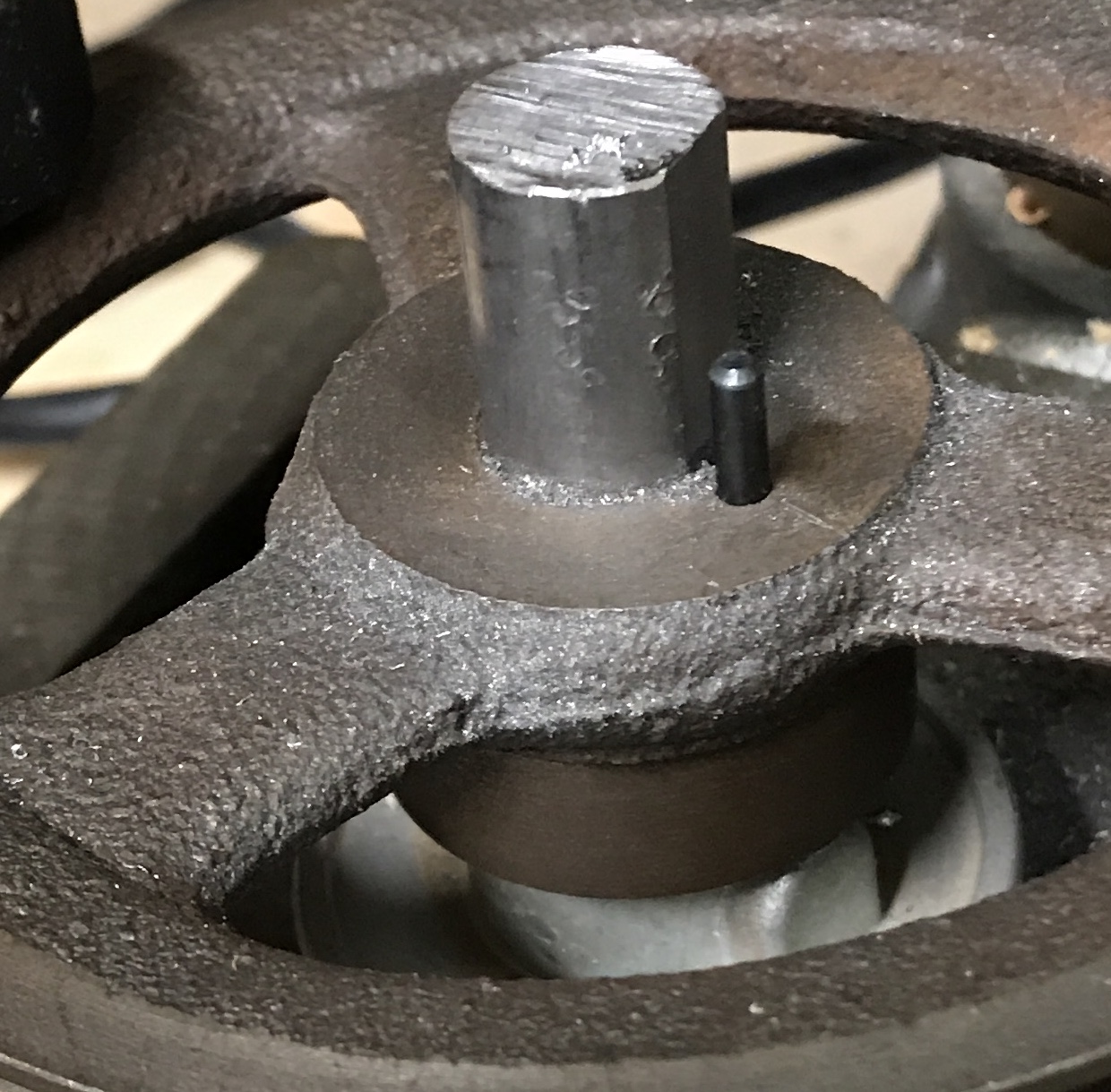
A pin for locking the two pulleys was made from a length of 1/8" drill rod. The rod was cut to the length of the drill as it was marked and removed from the hole. The ends of the rod were chamfered in the lathe. The pin was hardened by heating to cherry red and then quenching in oil. The pulley slid easily into the hole. The photos below show the pin partly inserted and fully inserted in the drilled hole.
The last leg! The column support no longer quite fit in the column this morning. It was returned to the lathe. An additional 0.02" was removed from the aluminum cap and it fit. The small pulley sits just above this aluminum cap, so a brass washer was made to minimize wear on this pulley. Just the outer rim touches. A 1/32" brass sheet was cut to 2" X 2". A 1/2" hole was drilled in the middle of this square. All of the burrs were removed. There was no point in making a mandrel to turn this circular. It was left square.
Everything was put together and installed in the column. The small idler pulley and the large spindle pulley were level. The small motor pulley was about 1/8" above the large idler pulley. The motor pulley was lowered until the two pulleys were level. The shaft was then removed and cut to fit. The end was faced, center drilled, drilled and tapped 10-32 for about 5/8".
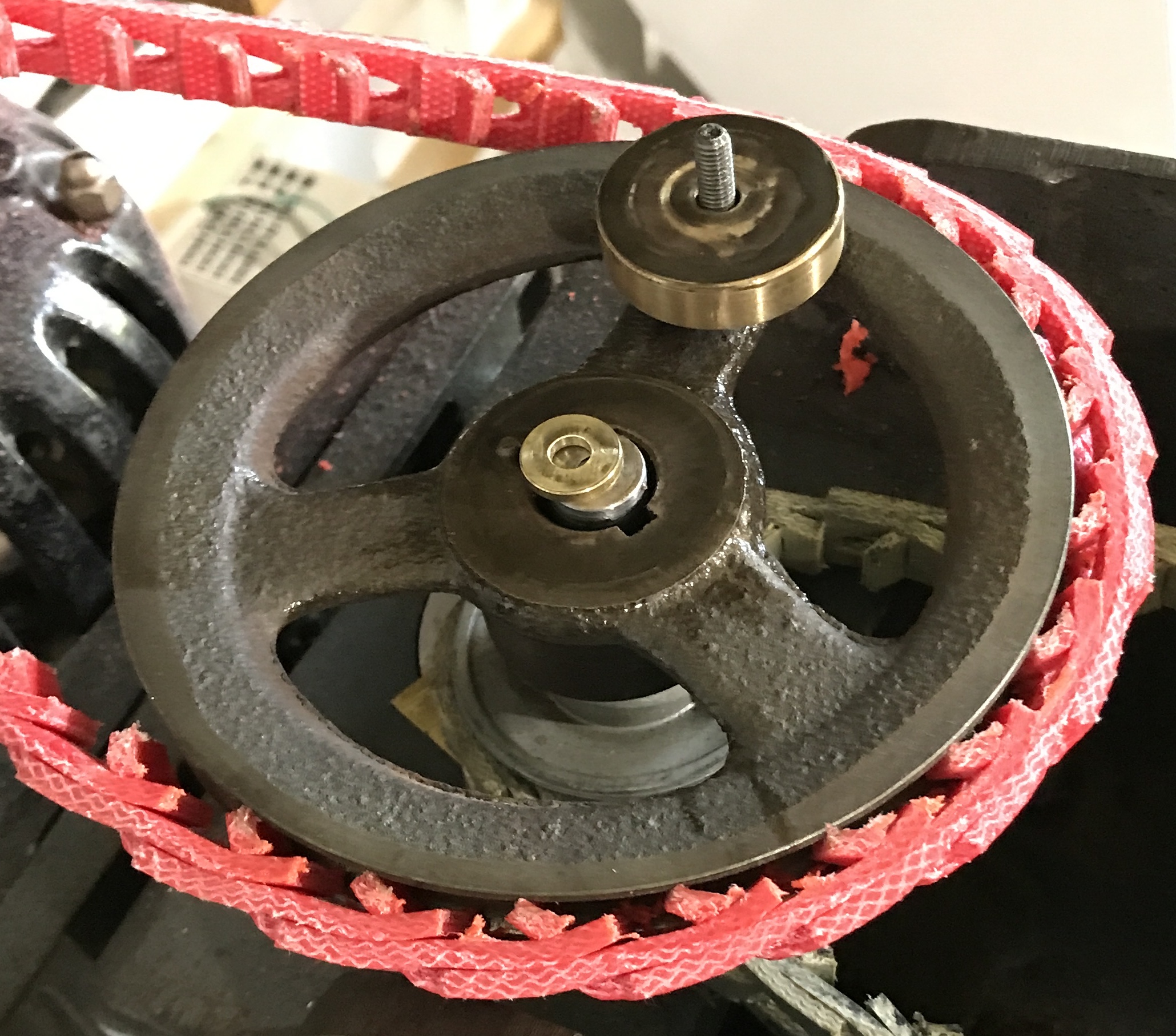
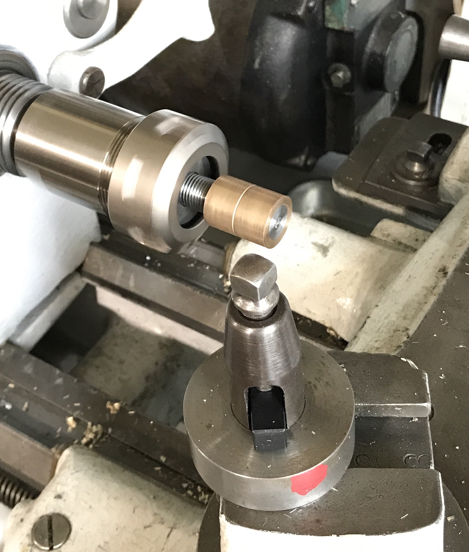
With all of the parts complete the idler pulleys and the brass washer were slid onto the shaft. The shaft was screwed into the column support and the lock nut was tightened. The brass cap was installed on the top of the shaft. When tightened down it was about 1/32" above the large pulley. Everything was thoroughly lubricated with the thinnest South Bend oil. The adjustable belt prepared previously for the idler to spindle pulleys fit. The belt from the motor to the idler needed two more links. Both belts were installed. The column support self-adjusted to even the tension. The first photo shows the installed idler pulleys. The second shows the top of the column support, the square brass spacer, and the two idler pulleys.
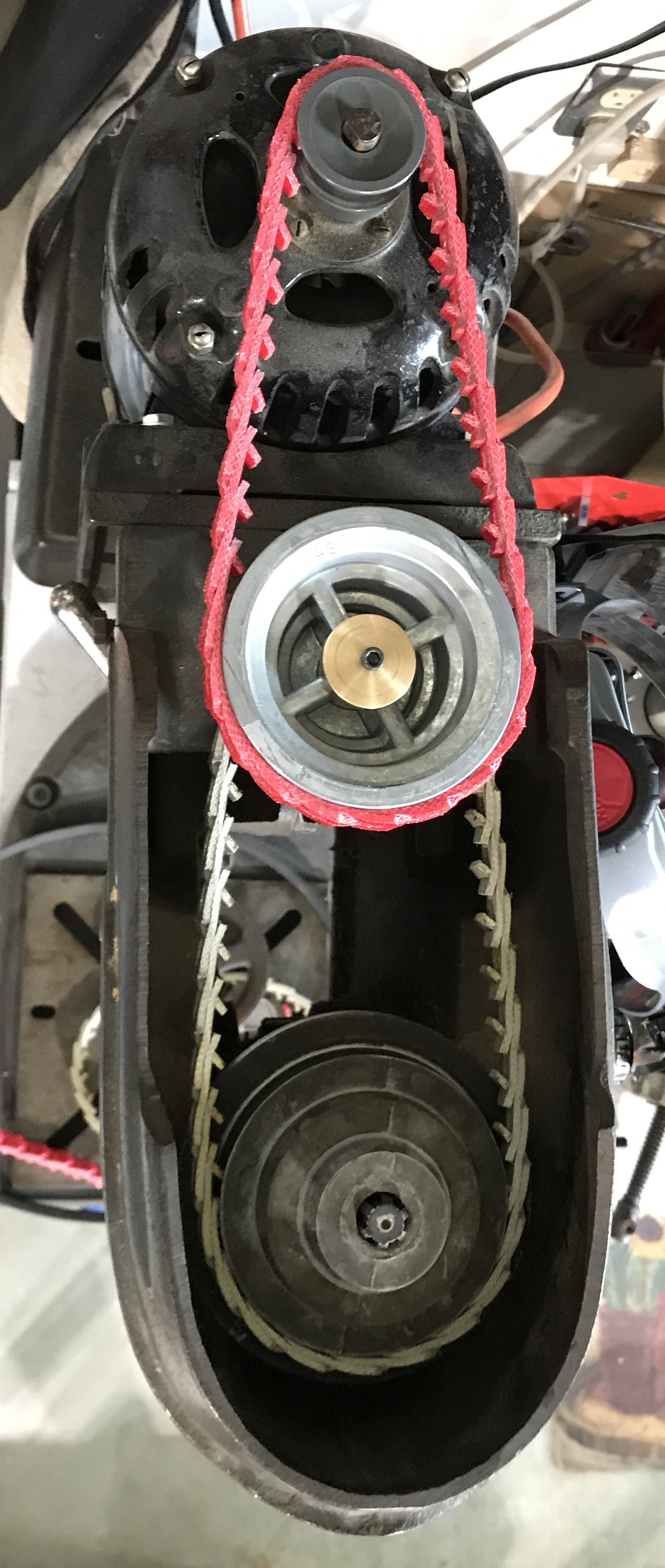
I was a little worried before testing the setup. I don't know how much torque the motor provides upon startup. I was worried the hardened 1/8" pin might break and allow the two idler pulleys to rotate independently. The drill press was plugged in. I flipped the switch and everything worked well. It is noisier than expected, but not enough to require ear protection. The spindle was noticeably slower. The RPM gauge was used to measure the speed: 510 RPM!!! I was quite impressed and thrilled. The drill press was once again useful. Like the South Bend lathe I will need to oil it frequently, especially under the small idler pulley.
I attempted to use a 2 1/4" Forstner bit to drill through walnut. A true test! The drilling began fine, but then the spindle quit moving and the belt was not moving on the still moving motor pulley. If left too long it actually begins to melt the belt. My first thought was that the belt was too loose. I removed the red belt and added four links. The motor was moved away from the housing using a long screwdriver for leverage. The belt was now tight on both pulleys. The spindle felt really tight. I was unable to turn it by hand. Sure enough the belt again began slipping on the motor pulley without any load on the spindle. I tried a few things to no avail. Unfortunately, the bolt that holds the left shaft for moving the motor in and out broke off. It will need to be drilled out. I am not sure what I can do with the machine at this point.
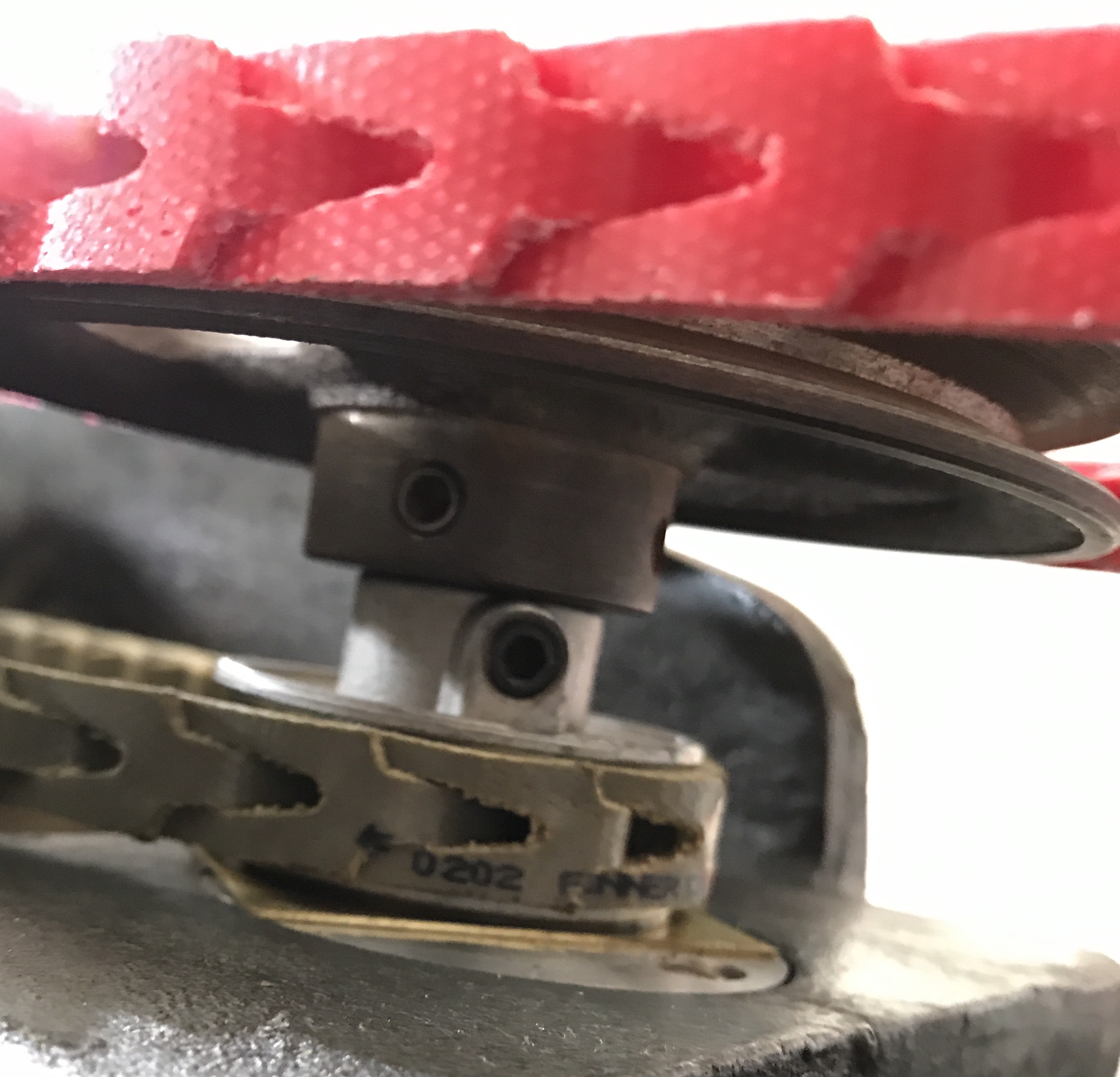
One more shot to repair the drill press. The red belt from motor to idler pulley was removed. The spindle still did not move. The belt from idler to spindle was removed. The spindle spins freely, but the idler is stuck tight!! I removed the screw holding the cap. It was very tight. As soon as it was loosened the idler spun freely. Upon removing the screw and cap it was clear that the shaft was below the level of the top of the pulley, so when the cap was tightened the pulley was pinched. A 0.08" brass washer was made from a 1/2" rod of brass after drilling a 13/16" hole. Inserting the washer and screwing the cap on tightly worked wonderfully! The picture below shows the cap, screw and new washer on location. Notice how the shaft is now above the level of the pulley. There is significant play in this axis of movement, mostly removed when the cap is tightened.